We developed TAMI using an iterative prototyping approach with significant user testing. This enabled gathering useful user feedback at each stage of development to inform design decisions for the following stages.
EARLY PROTOTYPES
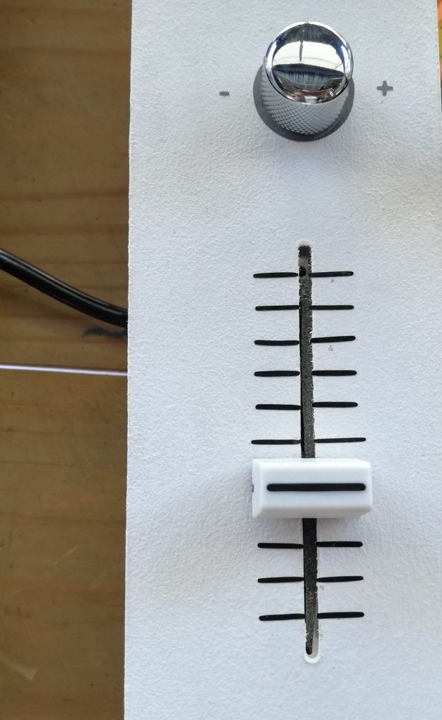
Sine and Cosine linear sliders
The first explorations about controlling sine and cosine through physical controllers included using two boxes featuring linear sliders. One box controlled sine and the second, cosine. Both boxes were connected to an Arduino board, that sent data to a Processing sketch in order to draw a sine-cosine within a Unit Circle. This solution proved that controlling sine and cosine separately was not the best approach since they are intrinsically related, something that was very relevant to understand. Also, with the sliders sine and cosine could reach their maximum values at once (1.0), something which never happens within a unit circle and can easily lead to confusion.
Rotational movement
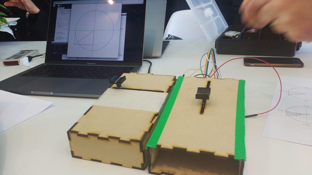
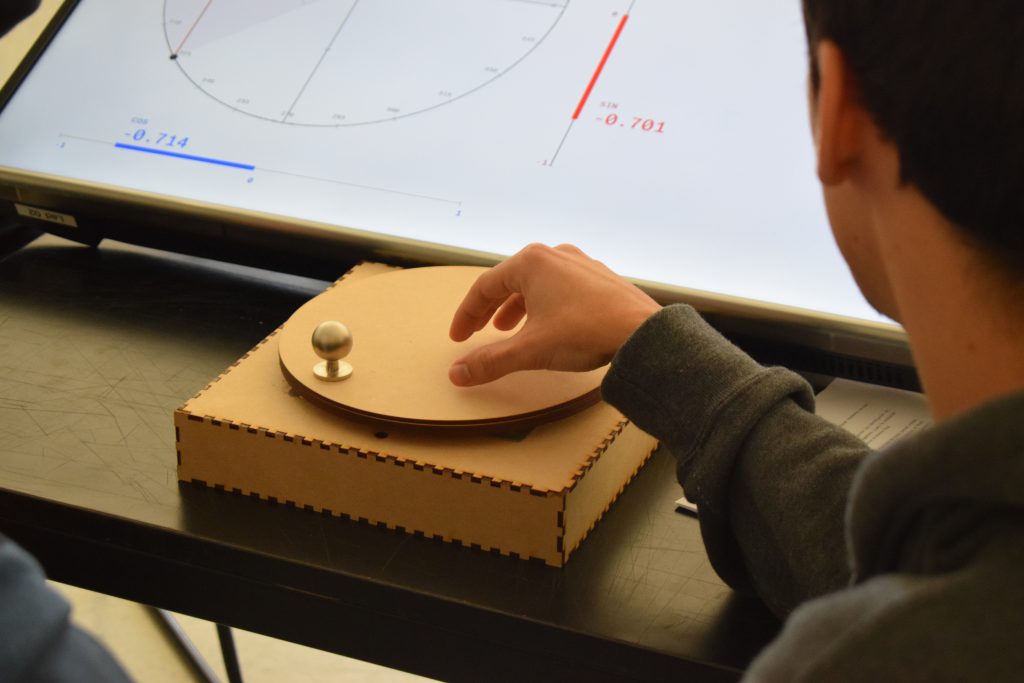
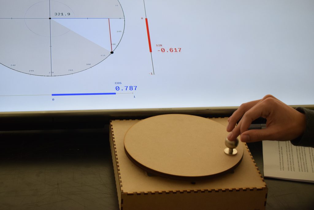
The following prototype took a better approach: instead of modifying sine and cosine directly, users modified the angle within the unit circle, which in consequence changed sine and cosine values. This approach enabled a better understanding the relation between angle values and the resulting sine and cosine values.
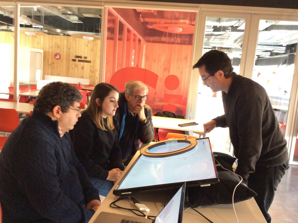
The new controller–similar to a turntable–could be rotated in both directions with the hand, thus increasing or decreasing the angle in the unit Circle. The circular piece was connected to a rotary encoder, capable of measuring angular values, with an accuracy of 0.03 degrees, and with marginal noise data. For this version, we started developing the software in OpenFrameworks, an open source C++ library. Visual feedback was now immediate and seamless, enabling users to focus more on the screen rather than on the control itself.
Although the controller worked correctly, its affordances resulted in a somewhat disjointed interaction. Users had a tendency to touch the screen to indicate or explain things, and then go back to move the rotary controller. This suggested that the controller and screen had to be integrated into one single structure.
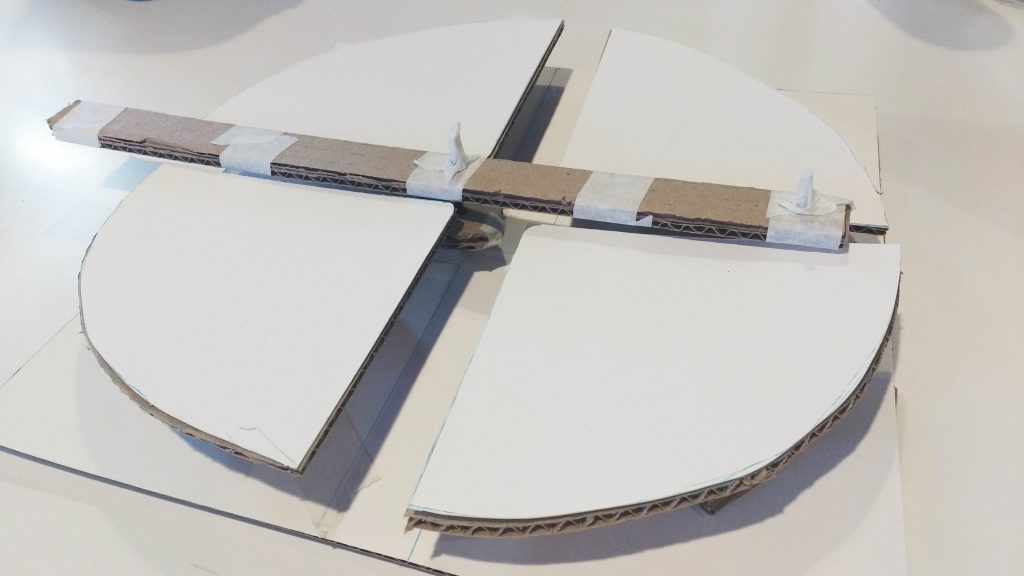
DIY bearing
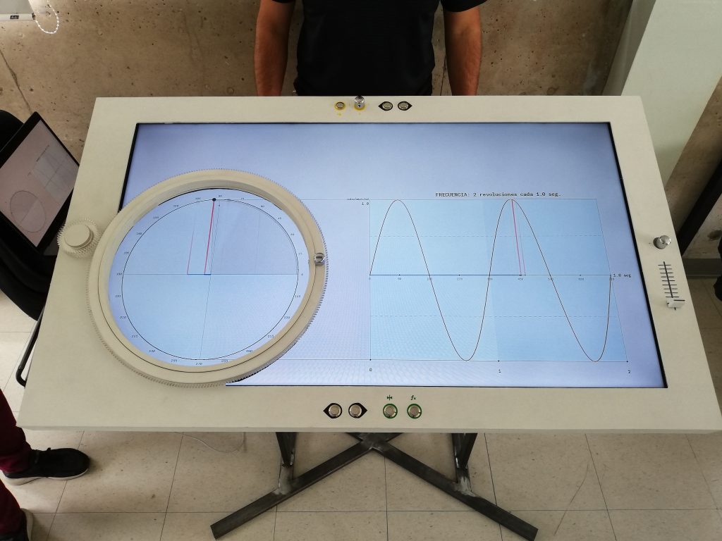
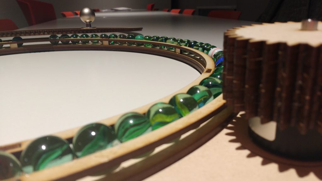
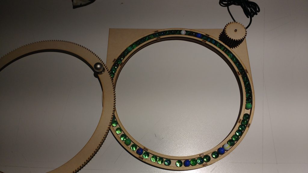
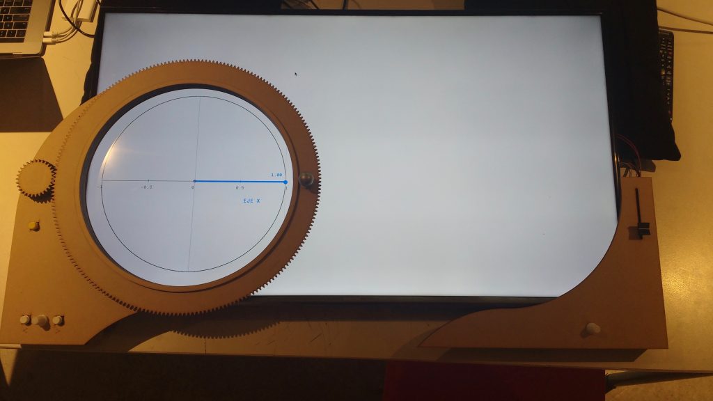
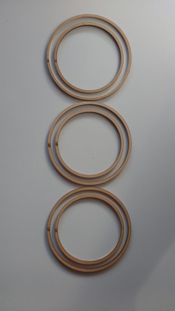
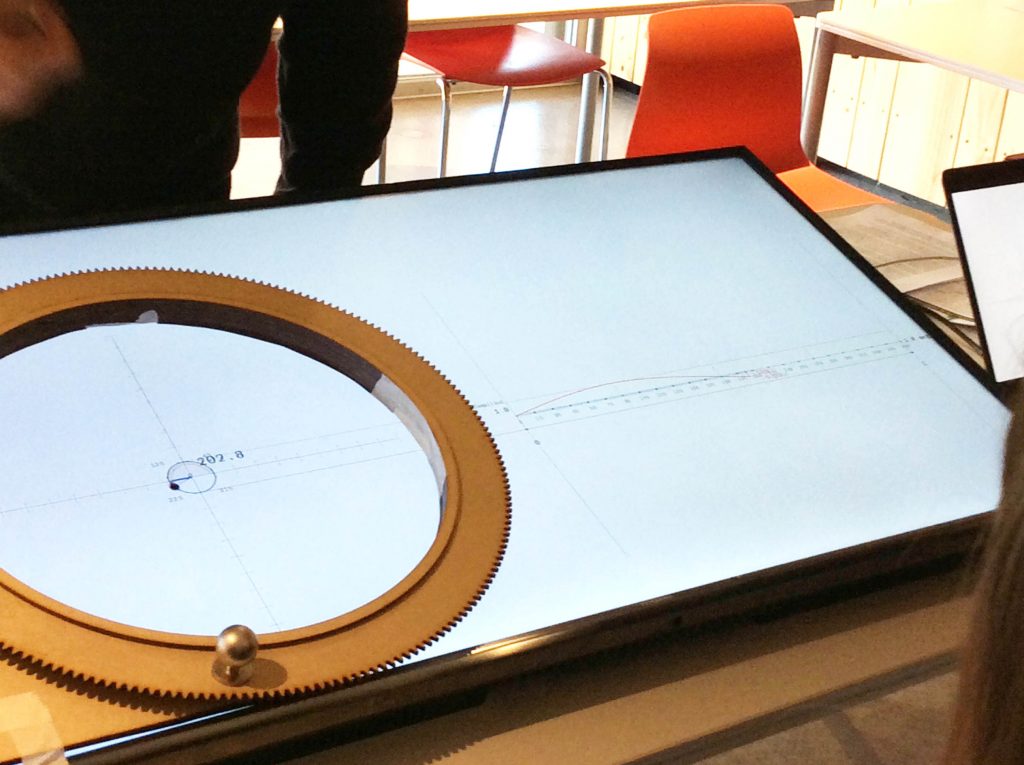
To place the controller on the screen it needed to leave space for the unit circle visualization. For this we built what we call the Rotary Wheel, a ring-like version leaving a circular space of 32 centimeters in diameter, where the unit circle could be drawn at an adequate scale. This configuration made the gesture more active and enabled a 1:1 scale representation of the digital and physical elements.
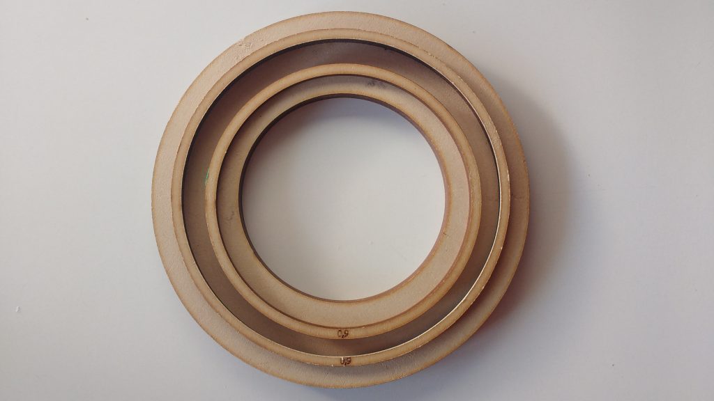
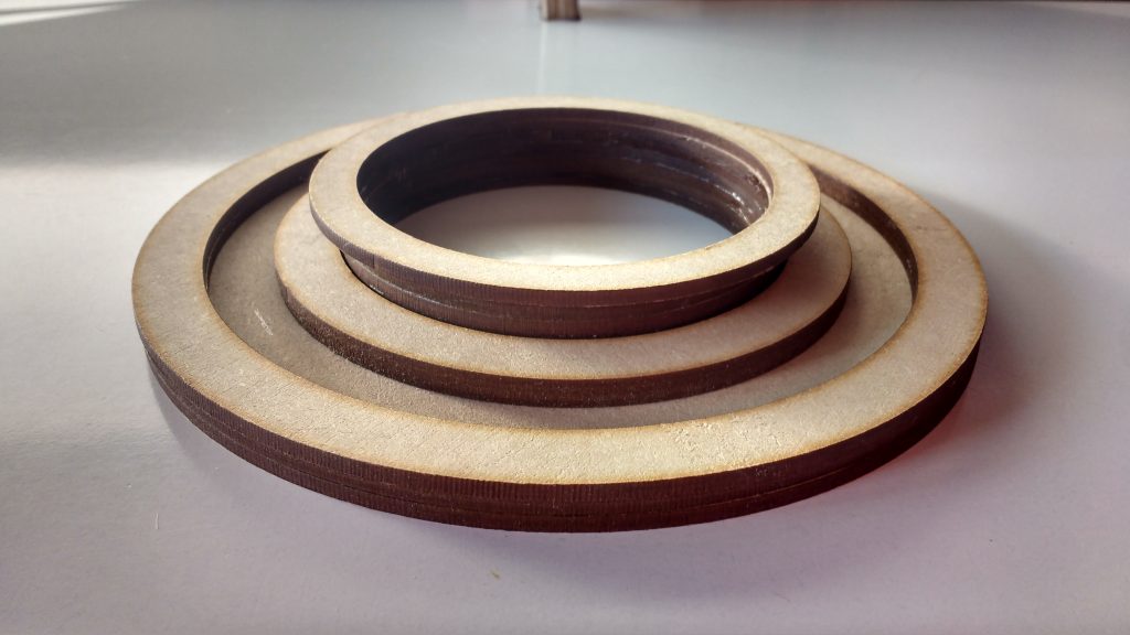
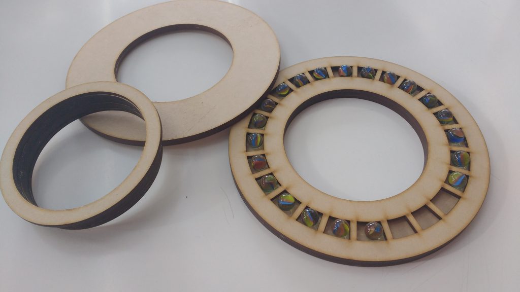
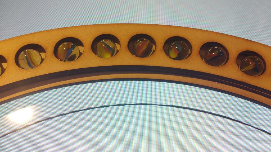
One of the challenges was to find a bearing big enough to fit such diameter. The available bearings were too bulky for our needs so we decided to design our own. Since we had to test this new design quickly without wasting much time and resources, we created a bearing that used laser-cut wood and glass marbles. Using a “sandwich” of three layers, marbles were contained in place.
PROTOTYPE 1
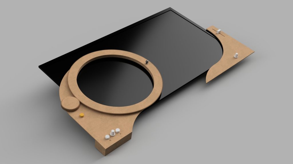
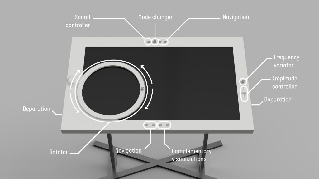
For this stage the “Rotary Wheel” was redesigned to make it thinner and was repositioned on the lower-left corner of the screen. New controllers were added to the interface to enable users to navigate the system on their own. A whole new section on the lower-right side of the screen was added to control amplitude and frequency (a knob and a slider) during a section that covered periodic functions during the experience.
PROTOTYPE 2
For this version, we focused on making a single, integrated structure, paying special attention to the aesthetics and operability. We aimed for something that did not distract users from what happens on the screen and from their interaction with their peers. The controls were reorganized, dividing them into two sides: student and teacher. With this configuration, the students could operate all the trigonometry-related controls, such as activating reflected angles visualization, toggling the visualization of equations, and navigating the system.
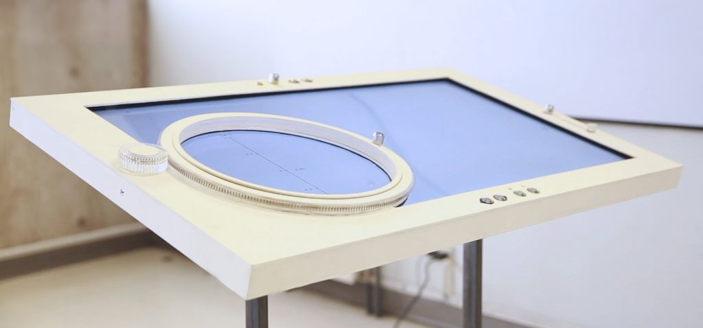
FINAL PROTOTYPE
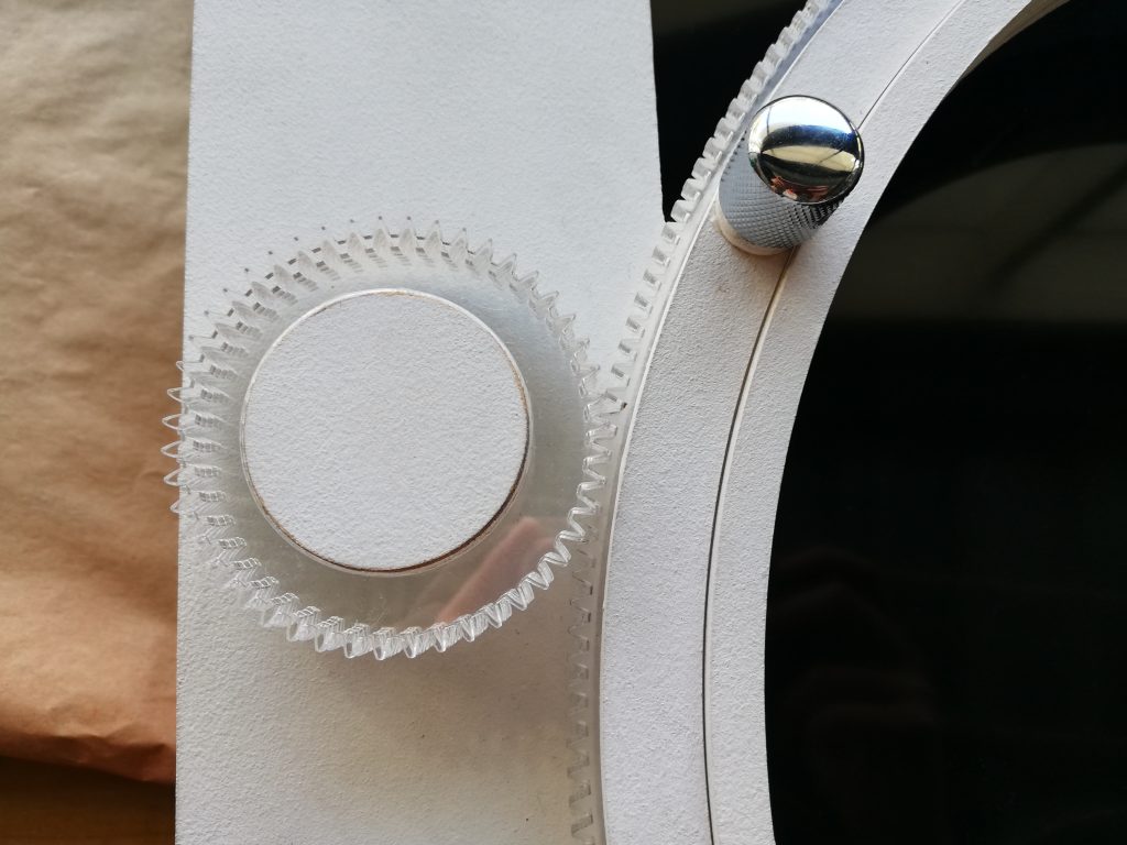
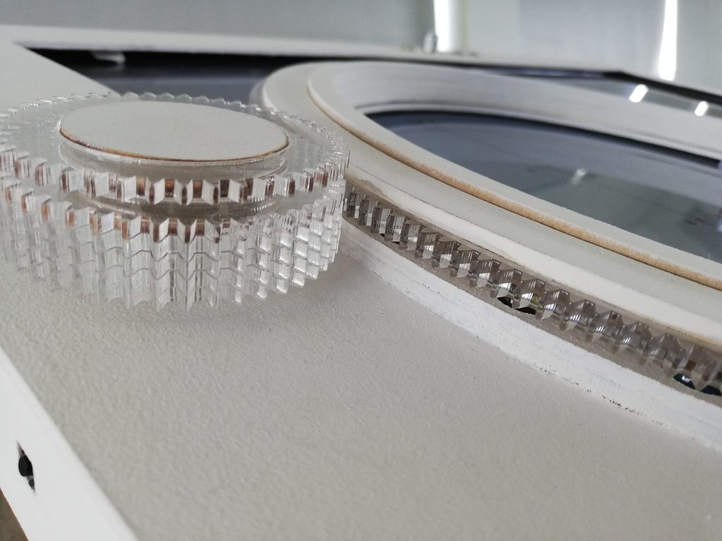
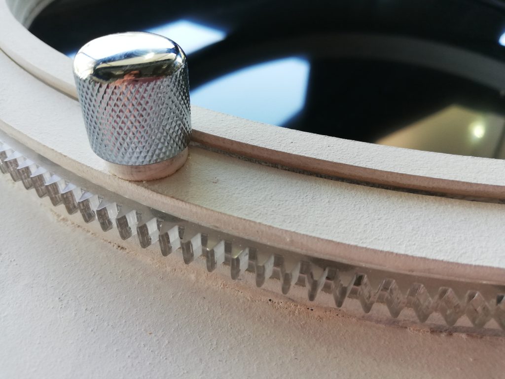
The final prototype was focused on enhancing the technical aspects of the interface. A larger screen was implemented and the whole structure was redesigned. The bearing was upgraded now integrating stainless steel 8mm balls and the mechanical parts of the Rotary Wheel were now made out of plexiglas. A brand new, larger slider was implemented to match the radius of the circle on the screen, for which we designed a custom system using a combination of gears and rails.
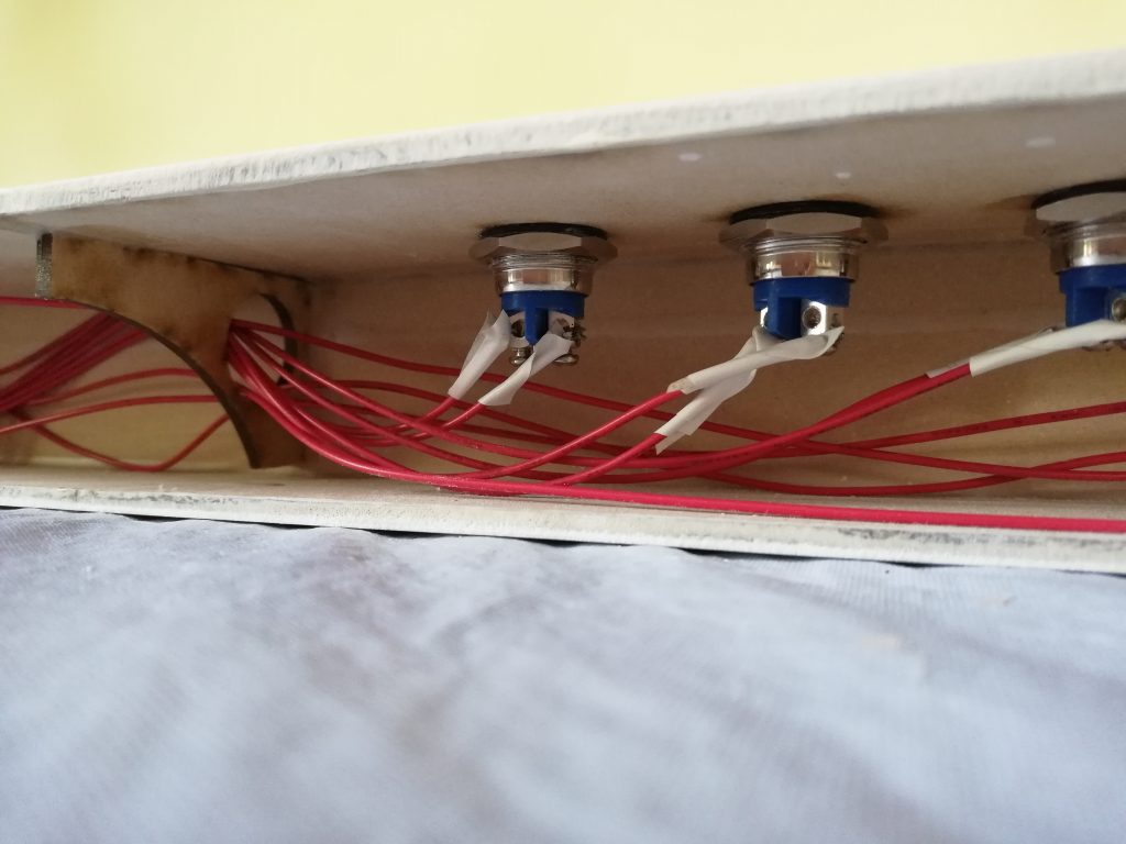
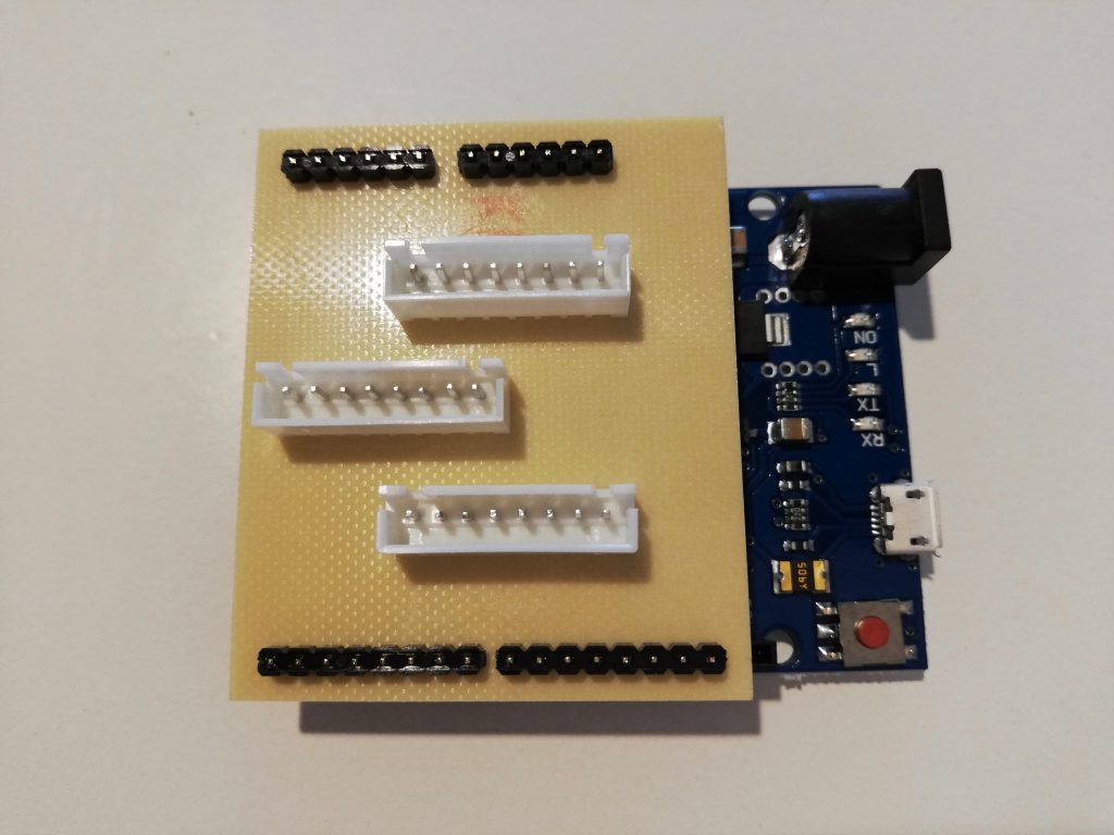
One important upgrade was the implementation of a Raspberry Pi as the main “brain” of the interface. The Raspberri Pi renders the external computer optional, making TAMI a standalone interface. The distribution of buttons for both the teacher and the students was redesigned, enabling a better and more intuitive operation.